RGB LED Web Server: Color Picker
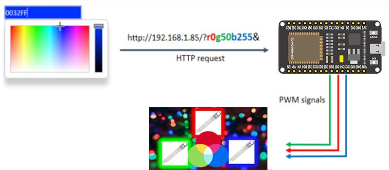
Pick any color in the browser; the ESP32 mixes it on an RGB LED with three PWM outputs.
Project_6_RGB_LED_Web_Server.ino, then open it in the Arduino IDE (setup: Foundation 3). Remember to set your Wi‑Fi credentials.
🎯 Objective
By the end of this project, you will:
- Understand how one RGB LED package holds three separate LEDs, and what "common cathode" means for wiring.
- Mix any colour by setting three PWM duty cycles, the same additive mixing a screen uses.
- Drive three PWM outputs at once with the Core v3.x+
ledcAttach()API. - Parse values out of a URL, extracting three numbers from a request like
/?r201g32b255&. - Combine two earlier projects: Project 3's PWM and Project 5's web server.
1 · How an RGB LED works
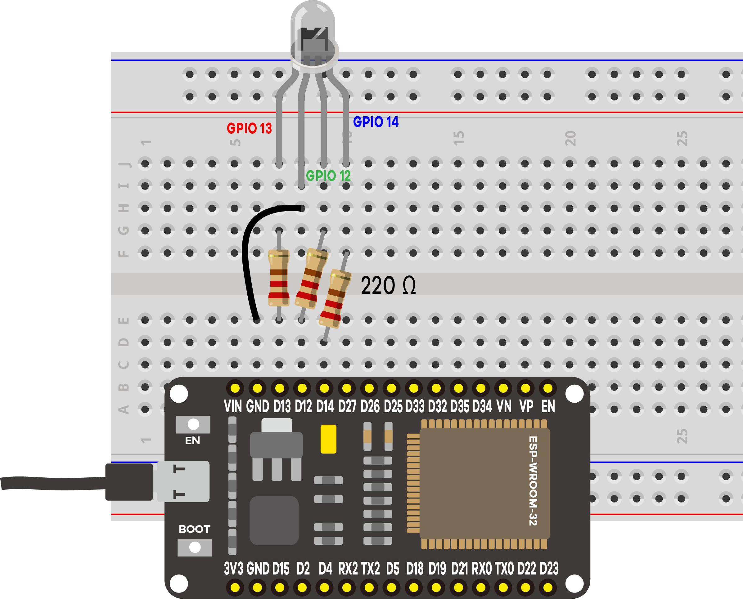
An RGB LED is three LEDs in one. The kit's are common cathode: all three share one negative leg, each color has its own anode:

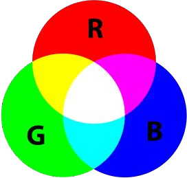
Setting each color's brightness with PWM mixes new colors:
2 · How the picker talks to the ESP32
Pressing Change Color requests a URL that encodes the color:
/?r201g32b255&
The ESP32 finds the r, g, b, & markers, slices out each number, and writes it to the matching PWM pin:
redString   = header.substring(pos1+1, pos2);   // "201"
ledcWrite(redPin, redString.toInt());           // 0..255
Setting up three PWM outputs
This is Project 3's PWM done three times, once per color. Each pin gets one ledcAttach() call in setup():
const int freq = 5000;        // 5 kHz, far too fast for the eye to see
const int resolution = 8;     // 8 bits -> 256 levels per color (0..255)

ledcAttach(redPin,   freq, resolution);   // GPIO 13
ledcAttach(greenPin, freq, resolution);   // GPIO 12
ledcAttach(bluePin,  freq, resolution);   // GPIO 14
ledcAttach(pin, freq, resolution) does the whole setup in one call, and ledcWrite() takes the GPIO pin as its first argument. The core picks a free internal PWM channel per pin, so you never name a channel yourself. Older Core v2.x code used ledcSetup() + ledcAttachPin() and wrote to a channel number; those functions no longer exist in v3.x+.8‑bit resolution is what makes the color picker line up so neatly: it hands you 0 to 255 per color, one duty‑cycle step per level, giving 256³ ≈ 16.7 million colors.
3 · Parts & wiring
| Qty | Part | Notes |
|---|---|---|
| 1 | ESP32 · breadboard · jumper wires | - |
| 1 | RGB LED (common cathode) | 4 legs |
| 3 | 220 Ω resistor | One per color |
4 · Upload & use
Set your Wi‑Fi ssid/password (2.4 GHz), upload, open Serial Monitor at 115200, press EN/RESET:
==============================================
 Project 6: ESP32 RGB LED Web Server
==============================================
RGB LED -> R:GPIO13  G:GPIO12  B:GPIO14
Connecting to Wi-Fi: MyNetwork
....
Wi-Fi connected!
Open this address in your browser:  http://192.168.1.42
----------------------------------------------
[WEB] Color set -> R:201  G:32  B:255
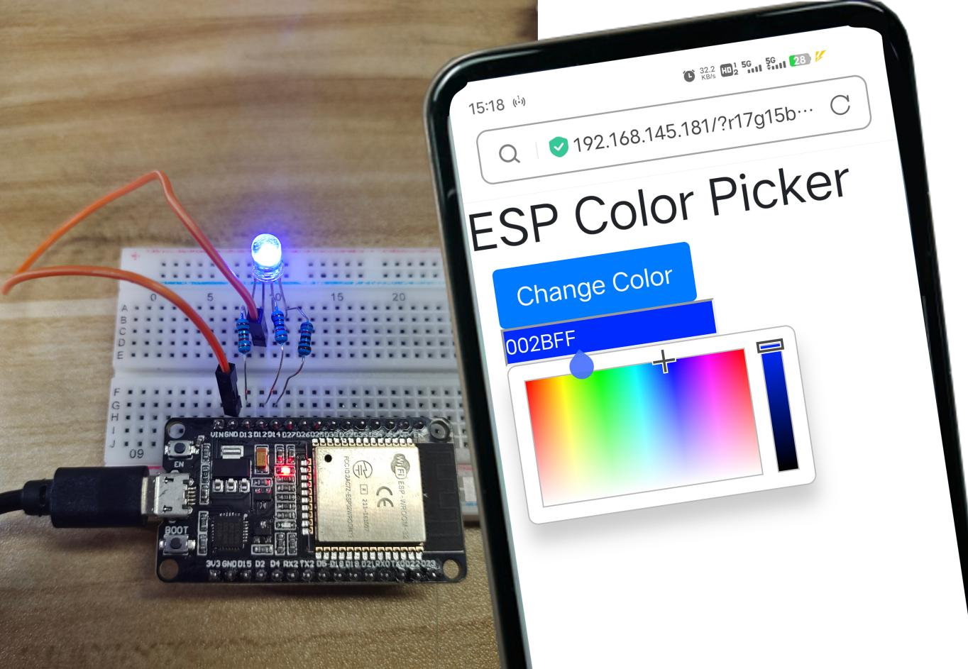
Open the address, pick a color, press Change Color. The log prints the exact R/G/B applied (added to the original sketch).
5 · Code Walkthrough: Understanding the Sketch
This is Project 5's web server with two changes: the outputs are PWM instead of on/off, and the request carries three numbers instead of naming a fixed action. Here are the parts that are new.
Step 1: Pins, PWM settings, and the strings that hold the colour
const int redPin   = 13;   // 13 corresponds to GPIO13
const int greenPin = 12;
const int bluePin  = 14;

const int freq = 5000;     // 5 kHz PWM
const int resolution = 8;  // 8 bits -> 0..255 per colour

String redString = "0", greenString = "0", blueString = "0";
The colours are kept as String rather than numbers because that is how they arrive: as text sliced out of the URL. They become integers only when written to the LED.
Step 2: three PWM channels plus Wi-Fi in setup()
ledcAttach(redPin,   freq, resolution);   // GPIO 13
ledcAttach(greenPin, freq, resolution);   // GPIO 12
ledcAttach(bluePin,  freq, resolution);   // GPIO 14

WiFi.begin(ssid, password);
server.begin();
Section 2's PWM setup followed by Project 5's Wi-Fi setup, unchanged. Nothing about hosting a page interferes with PWM: the LED PWM controller is hardware and keeps running while the processor handles requests.
Step 3: loop() parses the colour out of the URL
The HTTP skeleton (accept a client, read bytes, wait for the blank line, reply) is exactly Project 5's. The new part is what happens once a request has arrived:
// Request sample: /?r201g32b255&   ->  Red=201 Green=32 Blue=255
if (header.indexOf("GET /?r") >= 0) {
  pos1 = header.indexOf('r');       // find each marker
  pos2 = header.indexOf('g');
  pos3 = header.indexOf('b');
  pos4 = header.indexOf('&');

  redString   = header.substring(pos1 + 1, pos2);   // "201"
  greenString = header.substring(pos2 + 1, pos3);   // "32"
  blueString  = header.substring(pos3 + 1, pos4);   // "255"

  ledcWrite(redPin,   redString.toInt());
  ledcWrite(greenPin, greenString.toInt());
  ledcWrite(bluePin,  blueString.toInt());
}
The letters r, g, b and the final & are delimiters. Each number is whatever sits between one marker and the next, so substring(pos1 + 1, pos2) means "from just after the r up to the g". A crude hand-rolled parser, but it makes the mechanism visible in a way a library call would not.
The page is sent by the same client.println() calls as Project 5. It loads the jsColor picker, whose onFineChange handler rewrites the link's address as you drag, building the ?r…g…b…& URL that the code above takes apart.
Key concepts: what each line really does
| Code | What it does |
|---|---|
ledcAttach(pin, freq, resolution) | Enables PWM on one GPIO. Called three times, once per colour, so all three dim independently. |
ledcWrite(pin, value) | Sets one colour's brightness, 0 to 255 at 8-bit resolution. Three together make the mixed colour. |
header.indexOf('r') | Finds the position of a delimiter in the request text, or -1 if missing. |
header.substring(from, to) | Copies the characters between two positions: the digits of one colour value. |
redString.toInt() | Converts the text "201" into the number 201 that ledcWrite() needs. |
indexOf("GET /?r") >= 0 | Tells a colour request apart from the browser's plain first visit, so the LED is only rewritten when a colour was sent. |
6 · Demonstration
7 · Wrapping Up: What You've Learned
This project combines two earlier ones rather than teaching something entirely new, which is how most real devices get built.
- An RGB LED is three LEDs sharing one leg. On a common-cathode part that leg goes to GND and each colour gets its own resistor and PWM pin.
- Colour mixing is additive: red plus green makes yellow, all three at full make white, all off is darkness. Your eye does the blending.
- 8-bit resolution is not arbitrary: 0 to 255 per channel is exactly what the browser's colour picker produces, so the numbers pass through untouched.
- A URL can carry data, not just a command. Projects 5 and 7 name an action in the path; here the path carries three values.
indexOf()andsubstring()are enough to pull structured data out of text. Later projects hand this to a library (ArduinoJson in Project 12), but the idea is the same.- Hardware PWM runs independently of your code: the LED holds its colour while the processor serves pages.
8 · Troubleshooting
| Symptom | Likely cause | Fix |
|---|---|---|
| Page loads, no picker | No internet on the phone (CDN blocked) | Give the viewing device internet the first time |
| Only some colors work | A color leg mis‑wired | Check R/G/B → GPIO 13/12/14 |
| Colors inverted / odd | Common‑anode LED | This kit uses common‑cathode → shared leg to GND |
| Stuck on "Connecting…" | Wrong credentials / 5 GHz | Fix credentials; use 2.4 GHz |
'ledcAttach' was not declared | ESP32 Core v2.x installed | Update esp32 by Espressif Systems to v3.x+ in Boards Manager |