Analog Inputs: Reading a Potentiometer
Measure a range of voltage (0–3.3 V) as a number 0–4095 with the ESP32's ADC.
Project_2_ESP32_Analog_Inputs.ino, then open it in the Arduino IDE (setup: Foundation 3).
🎯 Objective
By the end of this project, you will:
- Understand the difference between digital and analog signals.
- Learn how the ESP32's Analog-to-Digital Converter (ADC) works.
- Read a potentiometer (variable resistor) and convert its analog voltage to a numeric value (0–4095).
- Use the
analogRead()function and the Serial Monitor to observe real-time sensor data. - Convert raw ADC readings into voltage using a simple proportional formula.
1 · Analog vs. Digital: How It Works
- A digital input sees only HIGH or LOW (Project 1).
- An analog input measures a continuous voltage 0–3.3 V and converts it to a number via the ADC.
The ESP32 ADC is 12‑bit, so readings run 0 … 4095:
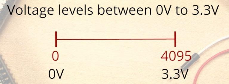
The ADC pin here
We use GPIO 4 ANALOG (ADC2, channel 0): the same physical pin that was a digital input in Project 1, now used with analogRead().
Which pins can do analog input?
Grab your ESP32 board and locate the pins highlighted with a red border in the figure below: these are your analog-capable pins:
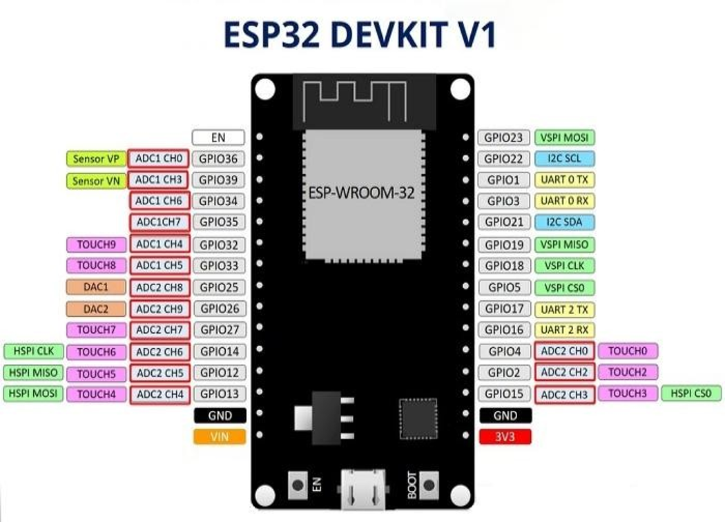
Notice that not every pin can read an analog signal. The red‑outlined pins are the ones connected to the internal ADC hardware. In this project we use GPIO 4, but you could use any of the other ADC pins just as well.
3 · Parts Required
| Qty | Part | Notes |
|---|---|---|
| 1 | ESP32 DEVKIT V1 · breadboard · jumper wires | - |
| 1 | Potentiometer (10 kΩ) | 3 legs: two ends + a middle wiper |
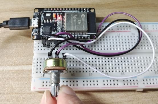
4 · Wiring the Circuit
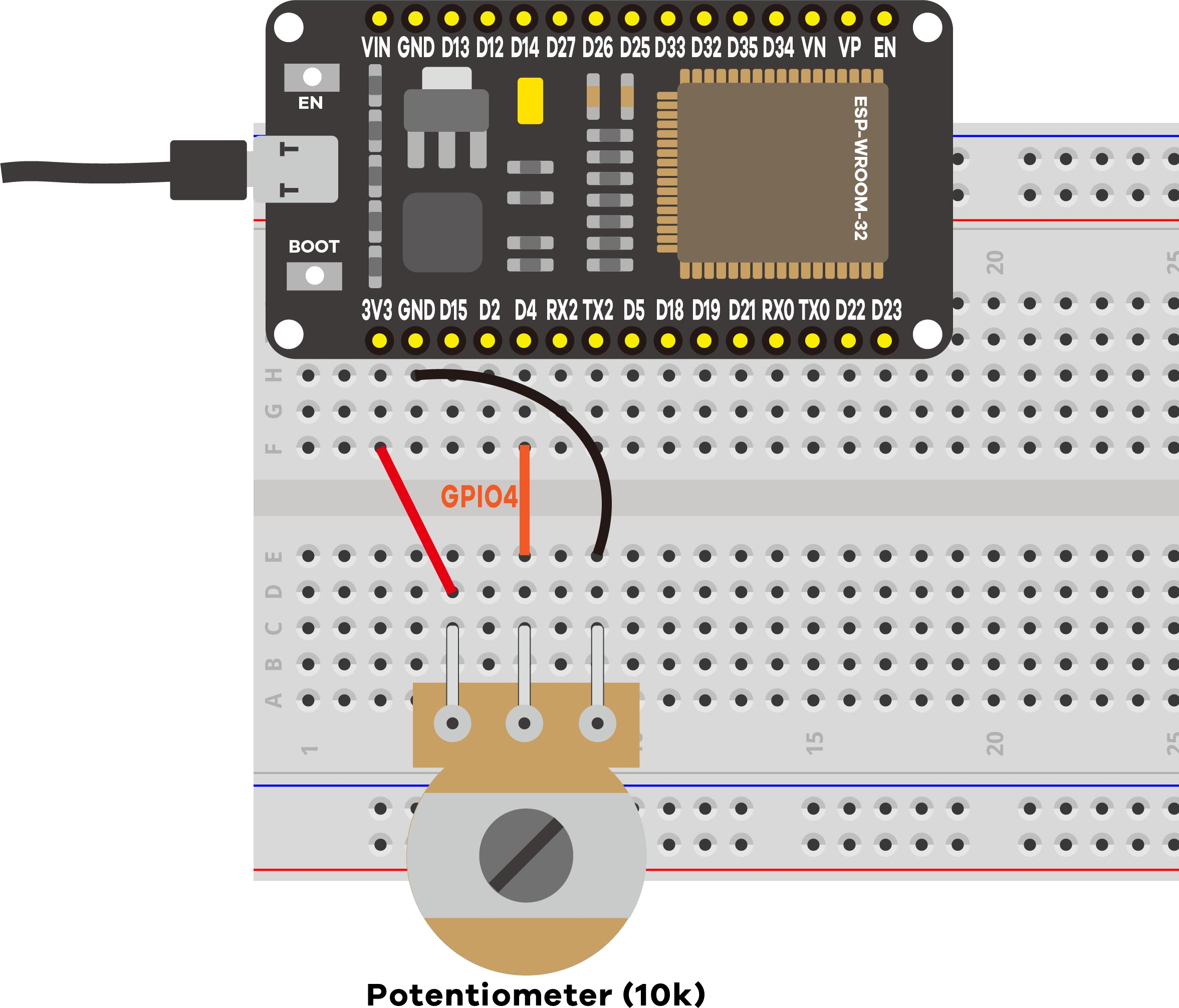
- One outer leg → 3.3 V
- Other outer leg → GND
- Middle leg (wiper) → GPIO 4
Turning the knob taps off 0 V → 3.3 V, and the ADC reports the matching 0–4095 value.
5 · Code Walkthrough: Understanding the Sketch
Let's walk through the key parts of the sketch so you understand what each line does and why.
Step 1: Pin definition & variables
// The potentiometer's middle leg (wiper) connects to GPIO 4
const int potPin = 4;    // ADC2, channel 0, an analog-capable pin

int potValue = 0;           // Variable to store the ADC reading (0–4095)
const int potPin = 4; gives the pin a human-readable name. Using a constant (const) prevents accidentally changing the pin number later. The variable potValue will hold whichever value analogRead() returns.
Step 2: one-time preparation in setup()
void setup() {
  Serial.begin(115200);     // Open the serial connection at 115200 baud
}
Serial.begin(115200) opens a USB link between the ESP32 and your computer. Without this, the Serial Monitor would stay blank. Think of it as turning on the communication channel.
Step 3: loop() reads → converts → prints → repeats
void loop() {
  // 1️⃣ READ the analog voltage on GPIO 4
  potValue = analogRead(potPin);          // returns 0 .. 4095

  // 2️⃣ CONVERT the raw number to actual voltage (0–3.3 V)
  float voltage = potValue * 3.3 / 4095.0;

  // 3️⃣ PRINT both values to the Serial Monitor
  Serial.printf("Pot: %4d / 4095   (~%.2f V)\n", potValue, voltage);

  // 4️⃣ WAIT 500 ms before the next reading
  delay(500);
}
Key concepts: what each line really does
| Code | What it does |
|---|---|
analogRead(potPin) | Measures the voltage on GPIO 4 and returns an integer 0–4095. The ESP32's built-in ADC hardware compares the input voltage to the 3.3 V reference and produces a proportional digital number. |
potValue * 3.3 / 4095.0 | A proportion: if 4095 = 3.3 V, then any reading × (3.3 ÷ 4095) gives the matching voltage. Example: 2048 × 3.3 ÷ 4095 ≈ 1.65 V (exactly half of 3.3 V). |
Serial.printf() | Prints formatted text to the monitor. %4d = integer, right-aligned in 4 columns; %.2f = decimal number with 2 digits after the dot. |
delay(500) | Pauses 500 ms (half a second). Without it, the ESP32 would read and print thousands of times per second: too fast to read. |
Expected output on the Serial Monitor
==============================================
 Project 2: ESP32 Analog Inputs (ADC)
==============================================
Potentiometer -> GPIO 4
12-bit ADC: 0 = 0 V ... 4095 = 3.3 V
Turn the knob and watch the value change.
----------------------------------------------
Pot:    0 / 4095   (~0.00 V)
Pot: 2047 / 4095   (~1.65 V)
Pot: 4095 / 4095   (~3.30 V)
6 · Understanding the ADC (Non-Linearity)
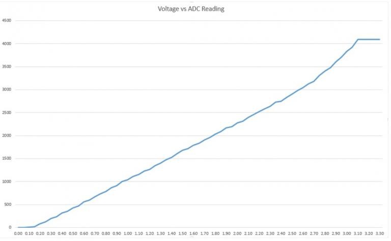
This matters for precise measurements; for a knob or light sensor it's fine.
7 · Demonstration
8 · Wrapping Up: What You've Learned
In this project you've learned how to read analog inputs using the ESP32 with the Arduino IDE. Here's a summary of the key takeaways:
- The ESP32 DEVKIT V1 DOIT board (30‑pin version) has 15 ADC pins you can use to read analog inputs.
- These pins have a 12‑bit resolution, which means you can get values from 0 to 4095.
- To read a value in the Arduino IDE, you simply use the
analogRead()function. - The ESP32 ADC pins don't have a linear behavior at the extremes of the voltage range. You'll probably won't be able to distinguish between 0 and 0.1 V, or between 3.2 and 3.3 V. Keep that in mind when using the ADC pins for precise measurements.
9 · Troubleshooting
| Symptom | Likely cause | Fix |
|---|---|---|
| Stuck at 0 or 4095 | An outer leg not on 3.3 V / GND | Recheck both outer legs |
| Value jumps randomly | Wiper not on GPIO 4 | Confirm middle leg → GPIO 4 |
| Monitor blank / garbage | Wrong baud | Set it to 115200 |
| Never reaches 4095 | Normal ADC non‑linearity | Expected near the top |